"I want the water surface to ripple." "I want the enemy to flash white when it takes a hit." Your goal is crystal clear — but everything you find online is HLSL code that reads like an incantation. Shaders may be the field with the biggest gap between what you want to do and the cost of learning it.
What closes that gap is Shader Graph — Unity's official node-based visual shader editor. Just by connecting nodes with wires, you can build glowing materials, rippling water surfaces, even hologram-style effects, without writing a single line of code.

What You'll Learn
- The building blocks of Shader Graph (Master Stack, Blackboard, properties)
- Basic workflow from creation to application, with texture and scrolling examples
- Changing values from scripts and when to use MaterialPropertyBlock
- Going further with Sub Graphs, Keywords, and Custom Functions
- Practical: building a shader that flashes white when hit
How It Differs from Traditional Shaders
Challenges of Traditional Shaders
- Programming knowledge is required
- Debugging is difficult
- Trial and error takes time
- High barrier for non-engineers
Advantages of Shader Graph
- No programming required - Just connect nodes
- Visually intuitive - The processing flow is easy to understand at a glance
- Real-time preview - See the results of your changes instantly
- Highly reusable - Create shared parts with Sub Graphs
- Supports URP and HDRP - Built-in RP support varies by version
Built-in RP support:
| Unity Version | Built-in RP Support |
|---|---|
| 2021.1 and earlier | Not supported |
| 2021.2 and later (Shader Graph 12+) | Built-In target supports both Lit and Unlit |
On the Built-In target, some nodes and settings that land first in the URP/HDRP targets aren't available. If behavior seems off, check the official docs for the target's support status (verified as of Unity 6 / 6000.0 for this article).
Building Blocks of Shader Graph
| Element | Description |
|---|---|
| Shader Graph asset | The file that stores the shader's configuration |
| Blackboard | The list of properties and keywords |
| Master Stack | The final output to the shader |
| Node | A unit of shader processing |
| Property | An external parameter of the shader |
| Sub Graph | A reusable part |
Types of Shader Graph Assets
| Type | Use |
|---|---|
| Unlit Shader Graph | Not affected by lighting (for UI and effects) |
| Lit Shader Graph | Affected by lighting (for PBR materials) |
Structure of the Master Stack
The Master Stack consists of two stages:
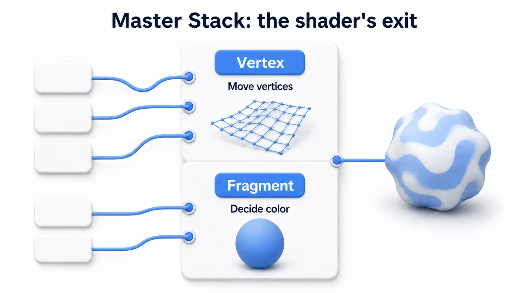
| Stage | Processing | Typical Uses |
|---|---|---|
| Vertex | Vertex shader processing | Vertex animation, position deformation |
| Fragment | Fragment shader processing | Color, textures, lighting |
Position port: By connecting to the Position port of the Vertex stage, you can deform vertex positions (rippling water surfaces, grass swaying in the wind, and so on).
PBR Parameters of the Lit Shader Graph
| Parameter | Description |
|---|---|
| Base Color | The base color |
| Normal | Normal map (surface detail) |
| Metallic | Metalness (0 = non-metal, 1 = metal) |
| Smoothness | Smoothness (0 = rough, 1 = glossy) |
| Emission | Emission color |
| Ambient Occlusion | Ambient occlusion (shadow intensity) |
| Alpha | Transparency (used with the Transparent setting) |
Setting Up Transparent and Semi-Transparent Materials
To create glass or semi-transparent materials:
- Select the Shader Graph and open the Graph Inspector
- Change Surface Type to
Transparent - Connect the transparency value to the Alpha port of the Master Stack (0 = fully transparent, 1 = opaque)
Key Graph Inspector settings:
| Setting | Options | Purpose |
|---|---|---|
| Surface Type | Opaque / Transparent | Opaque / transparent rendering |
| Render Face | Front / Back / Both | Which faces to render |
| Alpha Clipping | On / Off | Texture cutout |
| Two Sided | On / Off | Double-sided rendering |
| Cast Shadows | On / Off | Shadow casting |
Alpha Clipping: For cutout textures such as leaves or grass, enable Alpha Clipping and set the Alpha Clip Threshold.
Creating a Shader Graph and Basic Operations
Creating a Shader Graph Asset
- Right-click in the Project window
- Select
Create > Shader Graph > URP > Unlit Shader Graph - Double-click the asset to open the editor
Creating and Connecting Nodes
- Right-click in the workspace → Create Node
- Search for a node in the search field
- Drag from a node's output port to an input port on the Master Stack
Creating and Applying a Material
- Right-click the Shader Graph asset →
Create > Material - Drag and drop the created material onto an object
Dynamic Shaders with Properties
Adding a Property
- Click the
+button on the Blackboard - Choose the property type (Color, Float, Texture2D, etc.)
- Drag and drop the property into the Shader Graph window
Changing Colors from a Script
// Method 1: modify material directly (creates a material instance)
renderer.material.SetColor("_Main_Color", Color.red);

// Method 2: MaterialPropertyBlock (preserves batching, recommended)
var mpb = new MaterialPropertyBlock();
renderer.GetPropertyBlock(mpb);
mpb.SetColor("_Main_Color", Color.red);
renderer.SetPropertyBlock(mpb);
SRP Batcher and MaterialPropertyBlock (for how the SRP Batcher works, see Draw Calls and Batching):
- With the SRP Batcher enabled, using a MaterialPropertyBlock breaks SRP Batcher batching
- Small number of objects → MaterialPropertyBlock is fine
- Large number of objects → material instances may benefit more from the SRP Batcher
- Choose the approach that fits your use case
Important: About Reference names When accessing a property from a script, use the Reference name set on the Blackboard. Select the property in the Blackboard and check the Reference field in the Graph Inspector. By default it takes the form
_PropertyName(e.g.Main Color→_Main_Color; spaces are converted to underscores). You can freely change the Reference name in the Graph Inspector.
Shaders Using Textures
- Add a Texture2D property
- Add a Sample Texture 2D node
- Connect the property to the Texture input
- Connect the RGBA output to Base Color
Scrolling Textures
This is the entry point to "shaders that move." Flowing rivers, conveyor belts, drifting background clouds — feed the time from a Time node into the UV offset, and the texture scrolls endlessly.
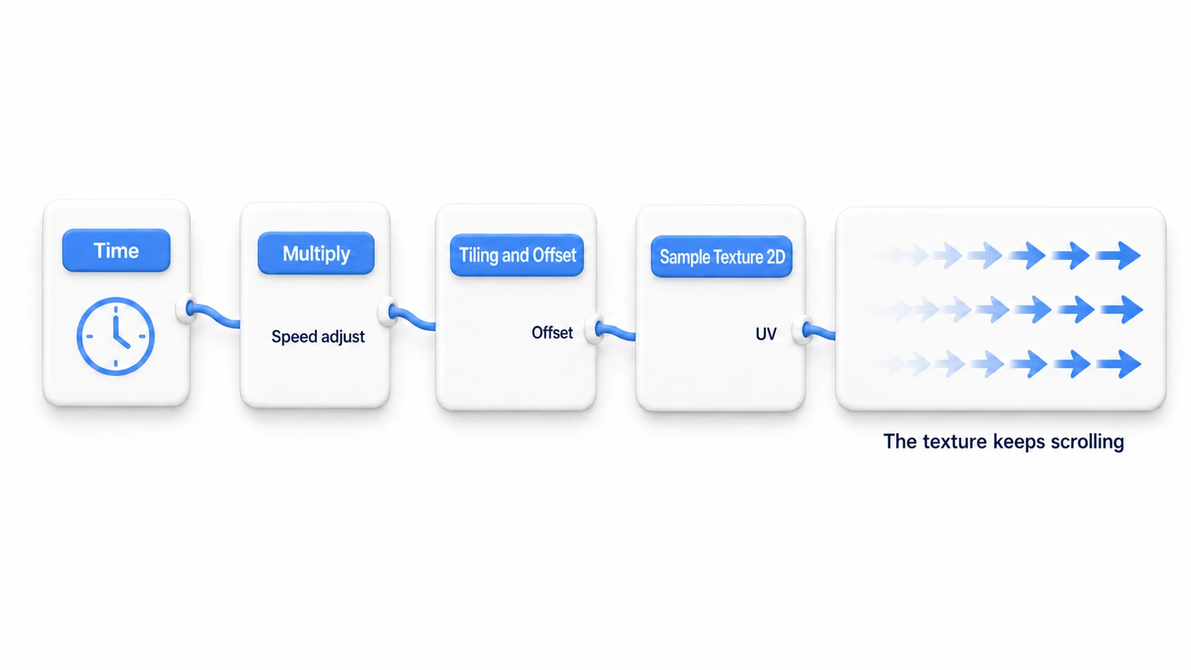
- Add a Time node (gets the current time)
- Add a Vector2 node (apply time to the X axis only)
- Add a Tiling and Offset node
- Connect the Vector2 output to the Offset input
- Connect it to the UV input of Sample Texture 2D
Use a Multiply node to adjust the speed.
Commonly Used Nodes
Input Nodes
| Node | Description |
|---|---|
| Time | Gets the current time (for animation) |
| UV | Gets the mesh's UV coordinates |
| Position | Gets the vertex position |
Texture Nodes
| Node | Description |
|---|---|
| Sample Texture 2D | Samples a texture |
| Tiling and Offset | Applies tiling and offset to UV coordinates |
Math Nodes
| Node | Description |
|---|---|
| Add, Subtract, Multiply, Divide | Basic arithmetic operations |
| Lerp | Linear interpolation |
| Clamp | Restricts a value to a range |
Procedural Nodes
| Node | Description |
|---|---|
| Noise | Generates noise |
| Checkerboard | Generates a checkerboard pattern |
| Gradient | Generates a gradient |
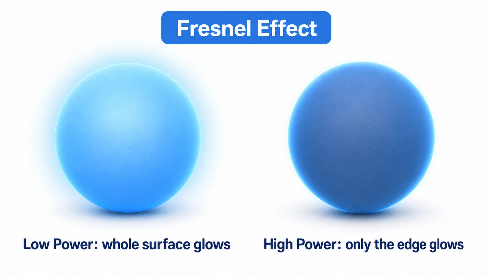
| Fresnel Effect | View-angle-based effect (rim lighting, holograms) |
Fresnel Effect Power value:
- Small values (1-2) → the effect spreads over a wide area (the whole surface glows)
- Large values (5-10) → the effect concentrates on the edges only (sharp rim light)
Creating Sub Graphs
A Sub Graph lets you bundle multiple nodes into a reusable part.
How to Create One
- Right-click in the Project window →
Create > Shader Graph > Sub Graph - Define the inputs and outputs in the Sub Graph editor
- Connect the processing nodes
- Save it and use it in other Shader Graphs
Use Cases
- Shared noise generation logic
- UV manipulation patterns
- Shared color conversion logic
Example: A UV Rotation Sub Graph
| I/O | Name | Type |
|---|---|---|
| Input | UV | Vector2 |
| Input | Angle | Float |
| Output | RotatedUV | Vector2 |
Processing: Use a Rotate node to rotate the UVs by Angle degrees and output the result as RotatedUV. You can reuse it for texture rotation animations and more.
Advanced Features
Keywords (Conditional Branching)
Keywords enable #ifdef-style conditional branching inside a shader.
- Click
+on the Blackboard → select Keyword - Choose the type: Boolean, Enum, or Built-in
- Drag the Keyword into the graph and a Keyword node is generated automatically
- Connect different processing to each output of the Keyword node
Optimization: With Keywords, different shader variants are compiled depending on the condition, letting you skip unnecessary processing.
Custom Function Node
This node lets you write HLSL code directly. Use it to add processing that Shader Graph alone can't achieve.
- Right-click →
Create Node→ search for Custom Function - Write the HLSL code in a file or inline
- Define the inputs/outputs and connect them
Next step: If you know HLSL, try tackling advanced effects with the Custom Function Node.
Common Problems and Solutions
| Symptom | Cause and Fix |
|---|---|
| Material turns pink | Shader compile error. Check the errors in the Graph Inspector |
| Material is completely black | Nothing is connected to Base Color, or the Normal Map format is not set |
| Not becoming transparent | Surface Type is still set to Opaque |
| Normal Map doesn't look purple | Set the Texture Type to "Normal map" in the texture's Import Settings |
Shader variants: Adding Keywords increases the number of shader variants exponentially (up to 2^n variants for n Boolean keywords). For mobile, it's recommended to strip unnecessary variants in Graphics Settings.
Practical: Building a Damage-Flash Shader
When you slash an enemy in an action game, when a bullet hits the boss in a shmup, when an attack lands in an RPG — that classic effect where the enemy flashes white for an instant is a perfect practice piece for Shader Graph. It brings together the whole flow you learned in this article: "create a property → wire up nodes → drive it from a script."
The mechanism is a single Lerp. Blend the normal color and pure white using FlashAmount (0-1) — 0 shows the normal look, 1 shows pure white, and bumping this value up for just a moment from a script gives you the "flash."
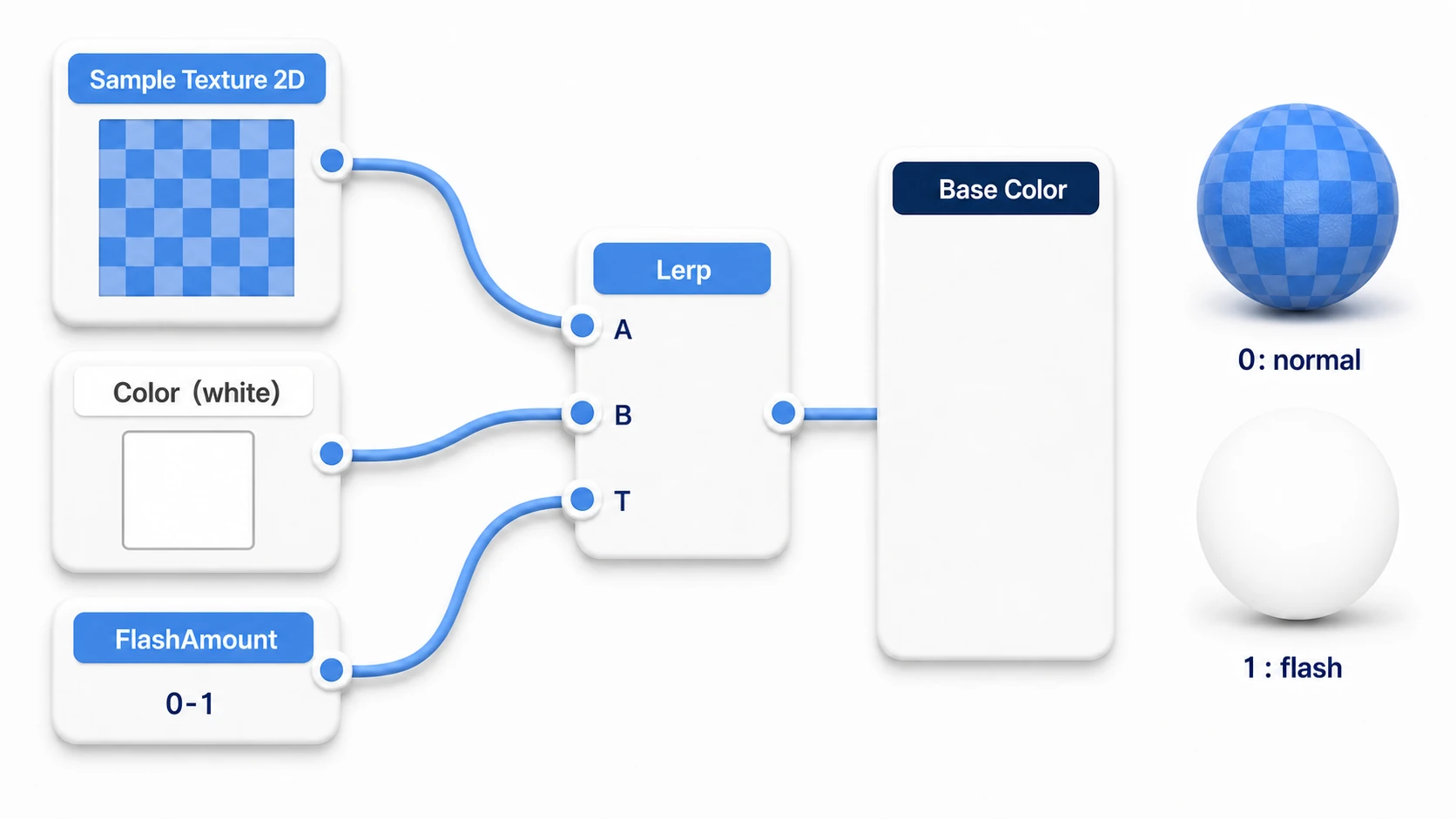
Building the graph (3 steps):
- Add two properties on the Blackboard:
MainTex(Texture2D) andFlashAmount(Float, Reference name_FlashAmount, default 0) - Read the texture with
Sample Texture 2Dand connect it to input A of a Lerp node. Connect a Color node (white) to B - Connect
FlashAmountto the Lerp's T input, and route the output to the Master Stack's Base Color
After that, all you do is drive _FlashAmount from a script. This is where the MaterialPropertyBlock introduced earlier pays off.
// DamageFlash.cs (attach to the enemy)
using System.Collections;
using UnityEngine;

public class DamageFlash : MonoBehaviour
{
    [SerializeField] private float flashDuration = 0.1f;

    private Renderer rend;
    private MaterialPropertyBlock mpb;
    private static readonly int FlashAmount = Shader.PropertyToID("_FlashAmount");

    void Awake()
    {
        rend = GetComponent<Renderer>();
        mpb = new MaterialPropertyBlock();
    }

    // Call this from your damage handling
    public void Flash()
    {
        StopAllCoroutines();
        StartCoroutine(FlashRoutine());
    }

    private IEnumerator FlashRoutine()
    {
        SetFlash(1f); // go pure white
        yield return new WaitForSeconds(flashDuration);
        SetFlash(0f); // back to normal
    }

    private void SetFlash(float amount)
    {
        rend.GetPropertyBlock(mpb);
        mpb.SetFloat(FlashAmount, amount);
        rend.SetPropertyBlock(mpb);
    }
}
Call damageFlash.Flash() from the enemy's damage handling and you're done. Because it uses a MaterialPropertyBlock, even with 100 enemies the material stays a single one — each enemy can flash on its own timing.
There are two key points: "build a look-switch from Lerp plus a 0-1 property" (not just white flashes — freeze, poison, stealth, and most other state effects take this same shape), and "touch script-facing values by their exact Reference name" (a typo in _FlashAmount won't raise an error — it just silently does nothing, so be careful). If coroutines are fuzzy for you, check that out too.
Summary
Shader Graph is a powerful tool that lets you create shaders without programming.
- Node-based - Build complex shaders just by connecting nodes
- Real-time preview - See the results of your changes instantly
- Properties - Adjust values from the material, and change them from scripts too
- Sub Graphs - Reuse shared parts
- The basic form of a state effect is Lerp plus a 0-1 property. The damage flash is your first step
Start with simple things like changing colors or displaying textures, then gradually move on to animations and effects. Your game's enemies — do they actually look like it "hurts" when they take a hit?
What to Read Next
- Want to check the prerequisites? → Render Pipeline Guide (Shader Graph requires URP/HDRP)
- Want to change the look of the whole screen? → Post-Processing Guide
- Starting from material fundamentals? → Materials and Shaders Basics